Today I was messing around with my electronics again.
The Georgia Tech structures lab has a Vishay 7000 strain gage DAQ designed to read several strain gages. I had been using it for my dissertation research, in experiments at GTRI. Recently, though, it was suggested that it might not be available for my research in the future. I believe that has since been resolved.
However, I had started a parallel effort involving designing and building a wheatstone-bridge amplifier circuit for a strain gage daq. If I couldn’t borrow a unit from school, and I wasn’t allotted the budget to purchase a commercial DAQ, I wanted to see if I might be able to build one from board-level parts.
Strain gages are small resistive patterns of wires, usually embedded in foil, which are attached to a surface. When the underlying surface deforms, minute changes occur in the resistance of the pattern. These changes in resistance are usually measured by means of a Wheatstone bridge. A Wheatstone bridge is a circuit that allows you to null out a reference resistance and measure changes in the resistance of the strain gage. The bridge consists of four resistors: Two on the balance arm, and two on the measurement arm. On the measurement arm, one of these is the strain gage. On the balance arm, one of the resistors is an adjustable resistor that allows zeroing of the signal.
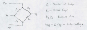
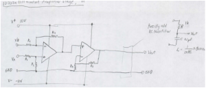
For a 350 ohm strain gage, with a gage factor of 2, for strains of 0.1 microstrain, changes in resistance are on the order of 7E-5 ohms: very small! These changes in resistance will result in changes in voltage (for excitation voltages of 2V) of 0.1 microvolts. In order to read this signal, the bridge excitation voltage must be amplified by 10000 times or so.
(PS: All you EEs out there: Stop laughing! This is my first time playing around with op-amps. I’m well aware that there may be issues with noise and variability in the resistors).
By the time the Vishay schedule was resolved, I had already designed a lot of the circuit, and ordered a lot of the parts. Today, just to see what I could do with the parts I had on hand, I began to assemble the Wheatstone bridge/amplifier unit.
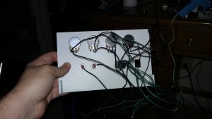
I 3d printed the front panel of the device: Here you can see the assembled front panel. The phone-jack is the input terminal for the strain gage (structures lab wires its strain gages into RJ25 plugs, which is what the Vishay uses for its input terminals). The potentiometers are a series of pots that allows the bridge to be balanced by adjusting R3 on the balance arm. The two bannanna-jacks are where I’ll probably plug in a real lab voltage meter after I give up on my DAQ.
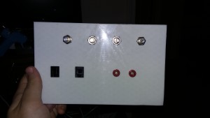
DAQ front panel
Electronic Cthulhu
PS – soldering leads to that RJ25 plug? Very fiddly. Check this out: As my Air Force friends might say, ‘rocket surgery’.
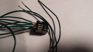
(PPS – quit laughing EEs! I didn’t have a nice breakout PCB to plug it into.)
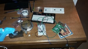
What I worked on mostly today: I wanted to see if I could build my own reader for analog signals such as the strain gages. I have an Arduino Mega, which has it’s own ADC built in, but I wanted to see if I could communicate with a commercial ADC chip using my Raspberry Pi (which only has digital IO pins). The Raspberry Pi is nice because I can command it to do things wirelessly by logging in via SSH. The Raspberry Pi is a full Linux PC, and you can program routines to interact with the IO pins in high level languages like Python.
Do you cut the red wire or the green wire? They’re all green wires! Muahahaha.
The ADC chip I’ve been using is the relatively cheap LTC1286. I managed to bit-bang the LTC and read the output from it successfully. There are a few things I might need to tweak. Right now, I am using a battery to supply voltage to the voltage reference pin – if I want to do this right, I’ll need to regulate the reference voltage somehow, as the refrence voltage governs the full-scale of the ADC. Without precise control of the reference voltage, you won’t have exact knowledge of what the binary output of the ADC means in terms of input voltage.
I’ll also need to play around with what I’ve been doing: There appears to be a lot of noise for something that is supposed to have 12 bits of resolution. (4096 levels between bottomed out and full scale, for those non-engineers reading this.) Here you can see me dialing the voltage divider up and down with the 100k pot attached to the circuit.
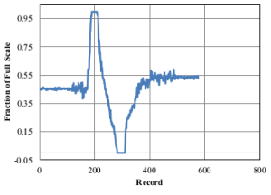
Noise. Also, signal.
Finally: The mess! I can’t wait until I have actual workspace, so I don’t have to use my bed as a bench.

Also, here is a link to the python code I wrote to bit-bang the ADC. (To send the right clock signals to read the output from the chip.)
test_ADCread2.py
Recent Comments: