All the stuff finally came in to try making my ADC board. Here it is:
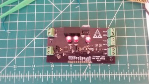
The board

The mess
This board is intended to be a general purpose lab DAQ board. Depending on how you set the resistors in the jumper slots, you can sense current, voltage (up to +/- 10V), and set the gain into the ADC and analog output. You can even route the analog output to something else. The way it is designed, it is +/-600V common mode tolerant and has a 130kHz bandwidth. (The main bottleneck being the high voltage differential chip)
Other features include:
- The world’s worst SMD solder job.
- Mysterious voltage divider behavior.
- A broken signal generator, so I had to test it with batteries.
:-P. I can fix that. It seems to work though, which is pretty good for my second PCB project.
Design Files:
Recent Comments: