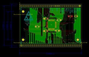
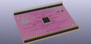
I made a simple breakout board for the STM32F732 microcontroller. I wanted the pins to be arranged in something like an organized fashion. The pin groups are arranged by name and function (PA0-PA15, PB0-PB15, PC0-PC15, and various control pins.) The STLink programmer should be able to plug right into the top-right four pins to program the controller. The controller should be easily powered by supplying 3.3V and ground to the VCC and GND pins on the top right.
This resulted in a bit of complexity in the routing (which you have to do by hand in KiCAD – no autorouter). I figured out a technique to make it all fit on the board. OSH Park came back with a price of $38 for a minimum run of 3 of these circuitboards. In two or three weeks, I’ll see how well this breakout board works.
This is part of a proof-of-work that I understand PCB technology, microcontrollers, and PCB CAD software. I’m not an electrical engineer by education, but I’ve picked up quite a bit of it in my work. The KiCAD project files can be downloaded from my site: STM_simplebreakout.zip
PS – yes, I know the ground plane is broken up, and held together by traces. This is my first attempt – I may be able to clean it up a bit in post.
Recent Comments: