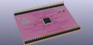
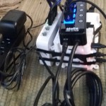
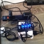
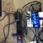
This device will not self destruct in 10 seconds (fingers crossed). So what is it?
It’s a super-computer! Well, okay, not entirely. It *could* be a cluster supercomputer, if these raspberry pi’s came with more ram. Each board actually has enough processing power to make a decent cluster. However, each board only has 1GB worth of RAM, and there’s no easy way to upgrade this – the architecture of these single board computers isn’t very extendable in that respect.
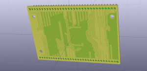
If you could get a raspberry pi with expandable memory slots, or if each came with, say 8GB of RAM, you could chain them to form a very nice supercomputer cluster.
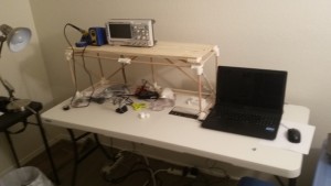
So why do I want it? (Because I’m a neeeerd.) It is set up like a supercomputer. Right now I have the one head node (hedgehog), and two computing nodes (hedgehog_n1 and hedgehog_n2). I intend to play around a bit with the high performance computing software libraries (MPI, petsc, and so on) at use at work on a “supercomputer” that I own and control. I also want to further self-educate on how to set up, administer, and write software for supercomputers.
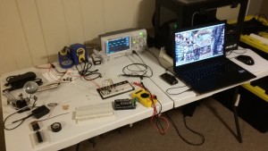
Further evidence of my nerd credentials: Stare into the abyss that is my desktop. Yes – that is an image of several VNC sessions with the nodes of my device, running inside a linux virtual machine, running inside my main windows PC.
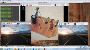
Computers all the way down!
The total cost of this project, btw, is ~$150. If I want to start throwing together a real supercomputer, I imagine the software and architecture will be the same, I’d just need to upgrade the hardware. (There are nice higher power small-form-factor fanless computers available from IBM, but they’re more expensive.) I figure I’ll shake the software products out first, then scale up.


Recent Comments: